Timber-frame box lintel over an opening
Drawn detail — timber frame box lintel (SAP Table K1 E2), with a referenced I-joist bay assembly
This report covers one junction detail and the component it depends on: I-joist bay (SJL45x200), modelled separately and reduced to an equivalent thermal conductivity in accordance with BR 497 §2.3.1, and the E2 Other lintels (including other steel lintels) junction that uses it. Both were calculated from the drawn cross-section using BS EN ISO 10211:2017, following the conventions of BR 497.
Components
Component 1: I-joist bay (SJL45x200)
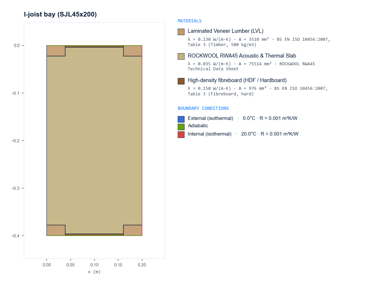
This component represents a repeating bay section through an engineered timber I-joist floor or flat roof zone, model-cut between joist centerlines. Structurally, the assembly is formed by an engineered I-joist comprising laminated veneer lumber (LVL) flanges joined by a slender high-density fibreboard (HDF) web member, oriented horizontally across the top and bottom bounds of the bay. Symmetrical half-flange LVL sections flank the perimeter at the opposing edges, representing adjacent joist profiles mirrored across adiabatic boundary lines. The primary cavity between the structural joist members is filled with a continuous core of ROCKWOOL RWA45 acoustic and thermal mineral wool insulation slab, which extends fully to envelope the I-joist profile. Heat flow is oriented perpendicular to the joist orientation, traversing from the warm internal boundary face on one side to the cold external boundary face on the opposing side, with top and bottom edges defined as adiabatic planes representing periodic structural repetition.
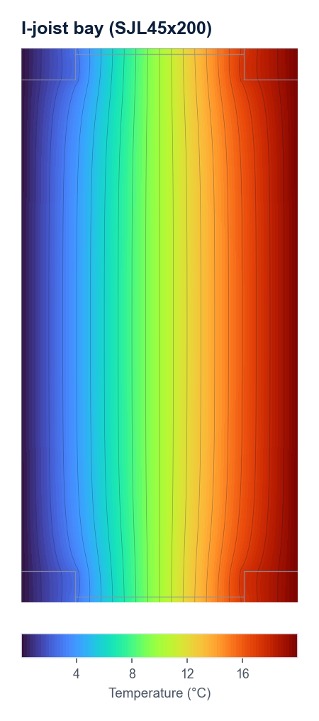
A two-dimensional numerical thermal model of the component was developed and solved using finite element analysis in accordance with BS EN ISO 10211. This rigorous numerical method was required because the cross-sectional geometry comprised non-uniform thermal paths that could not be simplified into an ordered, one-dimensional layered calculation under BS EN ISO 6946. Heat flow through the assembly was simulated to establish the steady-state thermal behavior across the interacting solid domains. The headline result from the finite element analysis was an effective thermal conductivity (λ) of 0.0394 W/(m·K). Based on the overall thermal resistance of the evaluated cross-section, the component achieved a resultant U-value of 0.1971 W/(m²·K). Thermal performance was governed primarily by the low conductivity of the ROCKWOOL RWA45 Acoustic & Thermal Slab, which accounted for the bulk of the thermal resistance within the cross-section. The overall heat transfer was further moderated by the thermal bridging effects of the higher-conductivity regions comprising Laminated Veneer Lumber and High-density fibreboard, which introduced multi-dimensional heat flux paths across the modelled assembly.
Junctions
ψ-Value Summary
| Ref | Label | K1 Default | Adopted ψ | fRsi | Status |
|---|---|---|---|---|---|
| E2 | Other lintels (including other steel lintels) | 1.000 | 0.041 | 0.97 | CALCULATED |
This table summarises the junctions addressed within this report. It is not a complete SAP 10.3 (13-01-2026) Table K1 schedule — Psiclops models individual junctions; compiling a full compliance schedule remains the responsible engineer's own task.
Junction 1: E2 — Other lintels (including other steel lintels)
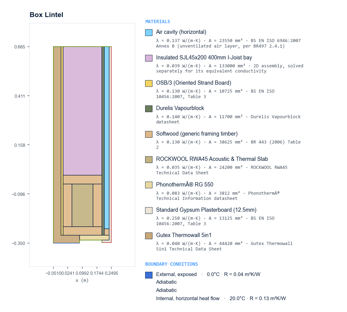
This construction details a box lintel junction within a high-performance timber-frame wall assembly, terminating at a window or door head opening. The primary wall zone above the opening features an engineered timber I-joist stud zone filled with insulation, sheathed externally with oriented strand board and an external wood-fibre continuous insulation board, and internally with an airtight vapour-control board. On the internal side of the primary structure, a continuous unventilated service cavity is lined with standard gypsum plasterboard, which forms the finished internal wall face. Directly above the head of the opening, the I-joist zone transitions into a structural timber box lintel assembly. This lintel is formed from softwood framing members arranged as continuous horizontal top, bottom, and inner plates enclosing vertical timber studs, with the core filled by a dense mineral wool acoustic and thermal insulation slab. Externally, the continuous wood-fibre insulation board wraps down over the outer face and extends around the lintel soffit, providing thermal break continuity to the external face. The underside of the lintel is further lined with a structural thermal insulation block (Phonotherm RG 550) to support the window or door frame installation, whilst the internal service void and plasterboard terminate cleanly against a horizontal timber head plate at the internal reveal.
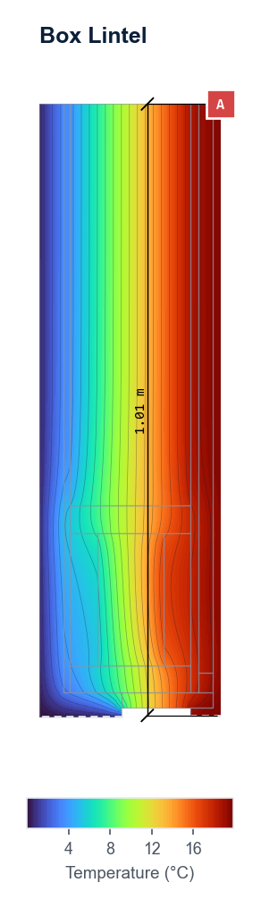
A linear thermal transmittance assessment was carried out for the junction designated as E2 — Other lintels (including other steel lintels), referenced in Table K1 of SAP 10.3 (13-01-2026). The evaluation was performed in accordance with the numerical modelling methodology outlined in BS EN ISO 10211:2017, adhering to the governing conventions set out in BR 497. The calculation determined a linear thermal transmittance (ψ-value) of 0.041 W/(m·K) for the modeled junction detail. When evaluated against the SAP 10.3 (13-01-2026) Table K1 default value of 1.000 W/(m·K) for an E2 junction type, the calculated performance demonstrated a substantial improvement. The modeled ψ-value of 0.041 W/(m·K) was significantly better than the standard default figure, confirming a marked reduction in localized transmission heat loss across the detail.
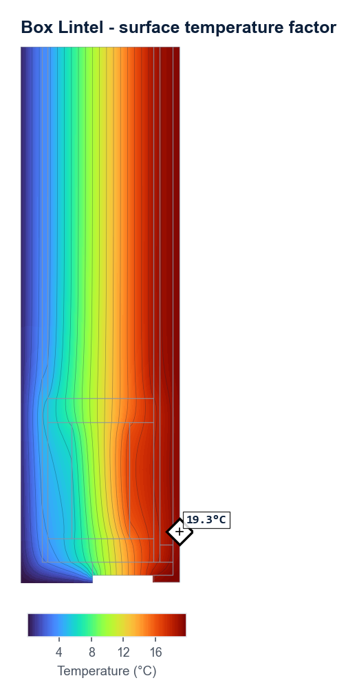
A thermal bridge assessment was performed to evaluate the risk of surface condensation and mould growth for the junction in accordance with the conventions set out in BRE IP1/06, applying standard assessment boundary conditions in accordance with BS EN ISO 13788:2012. The numerical modelling determined a minimum internal surface temperature, θsi,min, of 19.31 °C, from which a surface temperature factor, fRsi, of 0.966 was derived. The calculated temperature factor was evaluated against the critical threshold defined in the relevant UK building regulations and guidance for the assessed building type. With an fRsi value of 0.966 exceeding the minimum required design limit, the junction demonstrated robust thermal performance and successfully passed the assessment, indicating that the detail adequately mitigates the risk of surface condensation and mould growth.
Materials
| Material | λ W/(m·K) | Vapour resistance | Emissivity | Source |
|---|---|---|---|---|
| Laminated Veneer Lumber (LVL) | 0.13 | µ 250 | — | BS EN ISO 10456:2007, Table 3 (Timber, 500 kg/m3) |
| ROCKWOOL RWA45 Acoustic & Thermal Slab | 0.035 | µ 5 | — | ROCKWOOL RWA45 Technical Data Sheet |
| High-density fibreboard (HDF / Hardboard) | 0.15 | µ 150 | — | BS EN ISO 10456:2007, Table 3 (Fibreboard, hard) |
| Air cavity (horizontal) | 0.1366 | µ 1 | — | BS EN ISO 6946:2007 Annex B (unventilated air layer, per BR497 2.4.1) |
| Insulated SJL45x200 400mm I-Joist bay | 0.0394 | Sd 1.078 m | — | 2D assembly, solved separately for its equivalent conductivity |
| OSB/3 (Oriented Strand Board) | 0.13 | µ 150 | — | BS EN ISO 10456:2007, Table 3 |
| Durelis Vapourblock | 0.14 | µ 510 | — | Durelis Vapourblock datasheet |
| Softwood (generic framing timber) | 0.13 | µ 250 | — | BR 443 (2006) Table 2 |
| Phonotherm® RG 550 | 0.083 | µ 0 | — | Phonotherm® Technical Information datasheet |
| Standard Gypsum Plasterboard (12.5mm) | 0.25 | µ 50 | — | BS EN ISO 10456:2007, Table 3 |
| Gutex Thermowall 5in1 | 0.04 | µ 4 | — | Gutex Thermowall 5in1 Technical Data Sheet |
Download the solved geometry (JSON) — every polygon, boundary edge, material assignment and boundary condition exactly as calculated, including the conductivities derived for air spaces and referenced assemblies, so this example can be re-derived rather than taken on trust.
This is a fully static example — no live calculation was run to produce this page. It was generated once from Drawn detail — timber frame box lintel (SAP Table K1 E2), with a referenced I-joist bay assembly's own published construction and boundary conditions, using Psiclops's own calculation engine. Try your own junction for free →