Steel lintel with perforated base-plate (BR 497 Worked Example 3)
BR 497, Appendix B, Worked Example 3 (E1 — Steel lintel with perforated steel base-plate)
This report covers one junction detail and the component it depends on: Perforated steel base-plate, modelled separately and reduced to an equivalent thermal conductivity in accordance with BR 497 §2.3.1, and the E1 Steel lintel with perforated steel base plate junction that uses it. Both were calculated from the drawn cross-section using BS EN ISO 10211:2017, following the conventions of BR 497.
Components
Component 1: Perforated steel base-plate
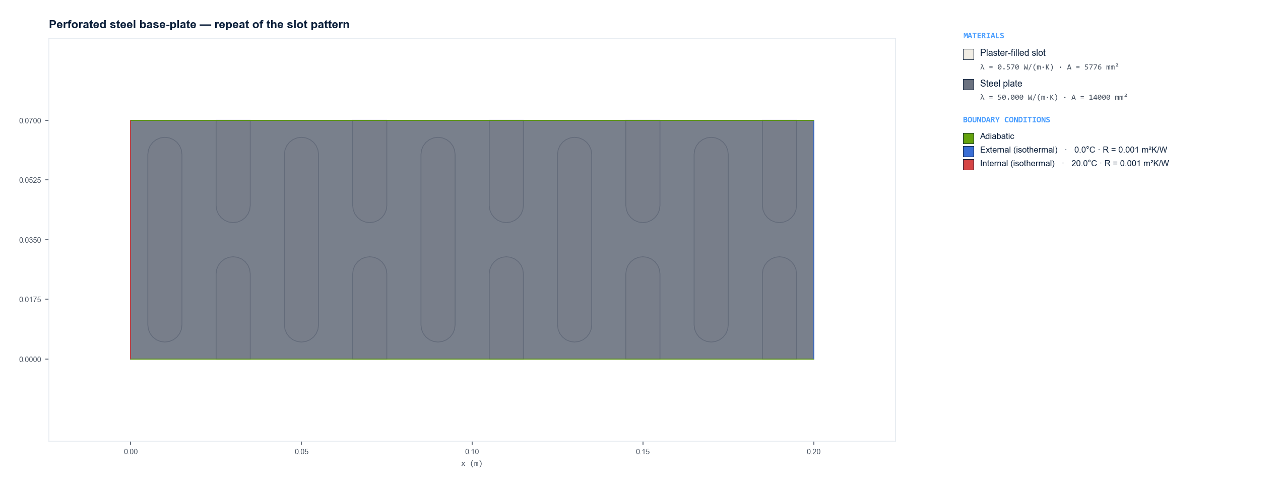
This construction represents a repeating section of a thermally broken or perforated steel base-plate component. The primary structural body consists of a continuous steel plate extending between the internal warm boundary on one face and the external cold boundary on the opposite face. The top and bottom longitudinal edges are treated as adiabatic boundaries, representing symmetry cut-planes through the repeating pattern of the plate. To attenuate lateral heat conduction across the metal cross-section, the steel plate is interrupted by a staggered array of elongated, rounded slots filled with plaster. These plaster-filled perforations run transversely across the plate in an alternating, interlocking arrangement, effectively creating a tortuous heat-flow path through the remaining web of steel between the warm and cold boundaries.
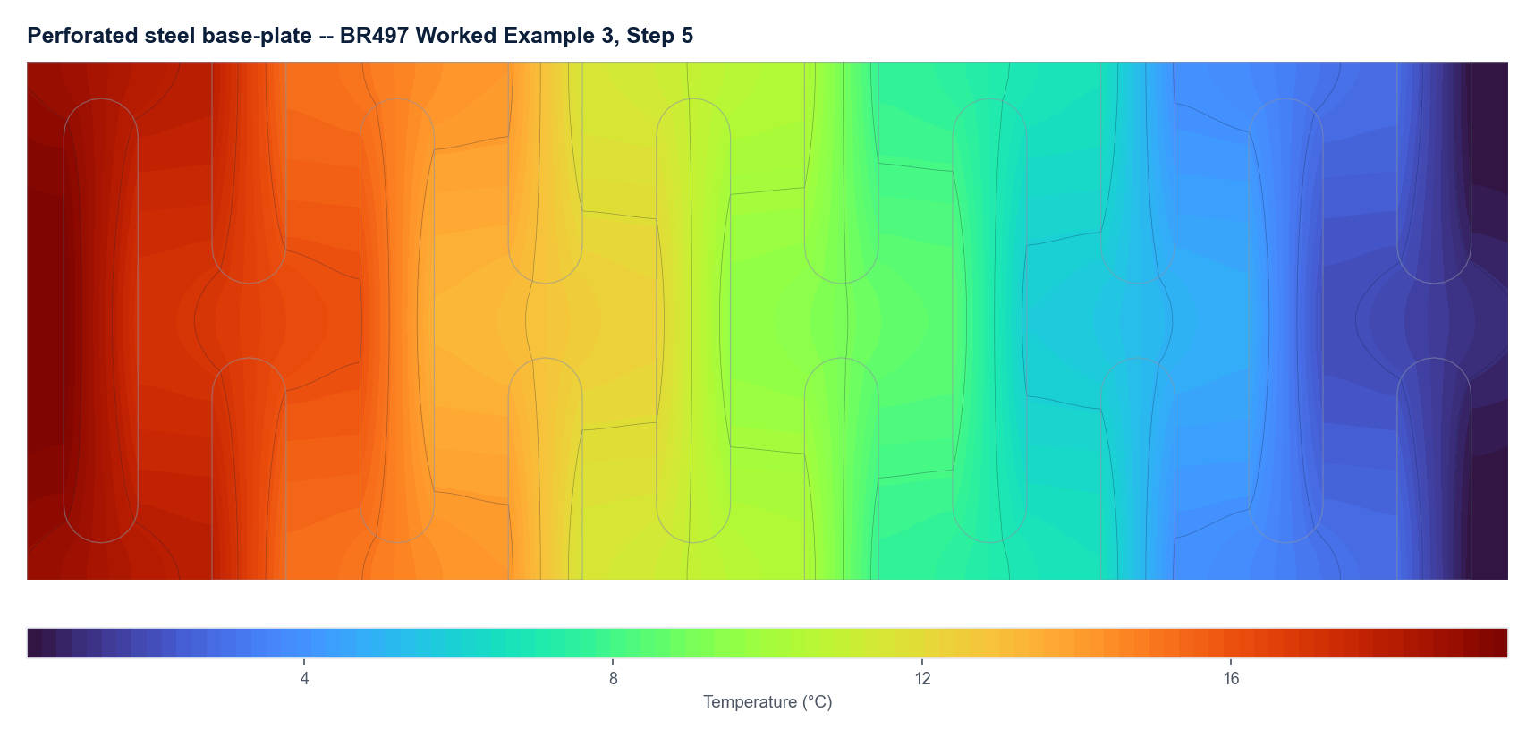
The thermal performance of the component was evaluated using a two-dimensional finite element model in accordance with BS EN ISO 10211. A numerical modelling approach was adopted because the complex internal cross-sectional geometry cannot be represented as an ordered stack of continuous planar layers under standard one-dimensional calculation methods such as BS EN ISO 6946. The finite element analysis simulated the two-dimensional heat flow pathways across the 200.0 mm wide cross-section, taking into account the geometric interaction between the constituent materials. The two-dimensional model resolved regions comprising a steel plate and plaster-filled slots. The substantial contrast between the thermal conductivity of the structural steel (50.0 W/m·K) and the lower conductivity of the plaster infill (0.57 W/m·K) established non-uniform heat paths across the section. The overall thermal transmission was predominantly governed by lateral heat flux around and through the plaster-filled slots within the steel matrix, which disrupted the high thermal transmittance otherwise associated with continuous metal. From the steady-state heat flow derived across the modelled cross-section, the primary output calculated was an effective thermal conductivity (λ) of 6.9322 W/m·K. This resultant equivalent property encapsulates the combined thermal behaviour of the steel plate interrupted by the plaster-filled slots, allowing the component to be represented accurately as a single equivalent homogeneous material within wider thermal bridge assessments.
Junctions
ψ-Value Summary
| Ref | Label | K1 Default | Adopted ψ | fRsi | Status |
|---|---|---|---|---|---|
| E1 | Steel lintel with perforated steel base plate | 1.000 | 0.412 | 0.76 | CALCULATED |
This table summarises the junctions addressed within this report. It is not a complete SAP 10.3 (13-01-2026) Table K1 schedule — Psiclops models individual junctions; compiling a full compliance schedule remains the responsible engineer's own task.
Junction 1: E1 — Steel lintel with perforated steel base plate
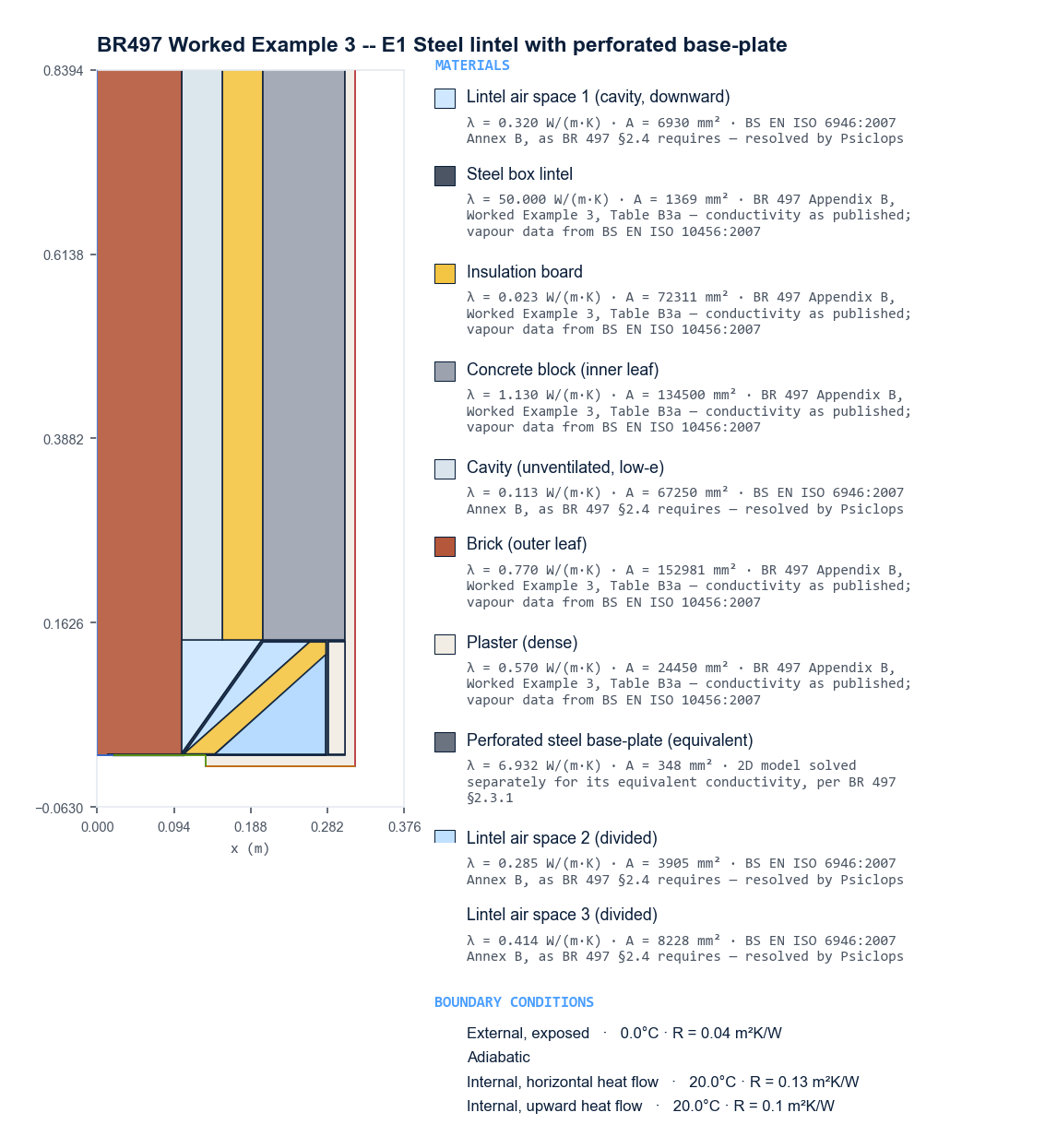
This junction represents an external cavity wall construction incorporating a thermally modelled steel lintel detail (conforming to standard BR497 Worked Example 3 / E1). Moving from the external cold side to the internal warm side, the main wall build-up comprises an outer leaf of masonry brickwork, a clear unventilated low-emissivity residual cavity, a continuous layer of rigid insulation board, and an inner load-bearing leaf of concrete blockwork finished internally with a layer of dense plaster. The upper boundary of the wall and lower base of the inner leaf are modelled with adiabatic boundaries representing planar cut-offs away from the thermal disturbance of the opening. At the window or door head, the conventional cavity construction terminates onto a composite fabricated steel lintel assembly supporting both leaves. A perforated steel base-plate extends beneath the cavity opening, bridging across to the outer brick skin. Above this base, a fabricated steel box lintel carries the inner masonry leaf, featuring an internal inclined web that divides the lintel profile into internal air cavities alongside an integrated diagonal infill of rigid insulation board. The clear cavity space immediately above the lintel base is modelled as a downward heat flow air zone, directly bounded by the outer leaf brickwork and the partial-fill cavity insulation above. Dense plaster continues down the internal face, returning under the inner lintel soffit to meet the window head boundary.
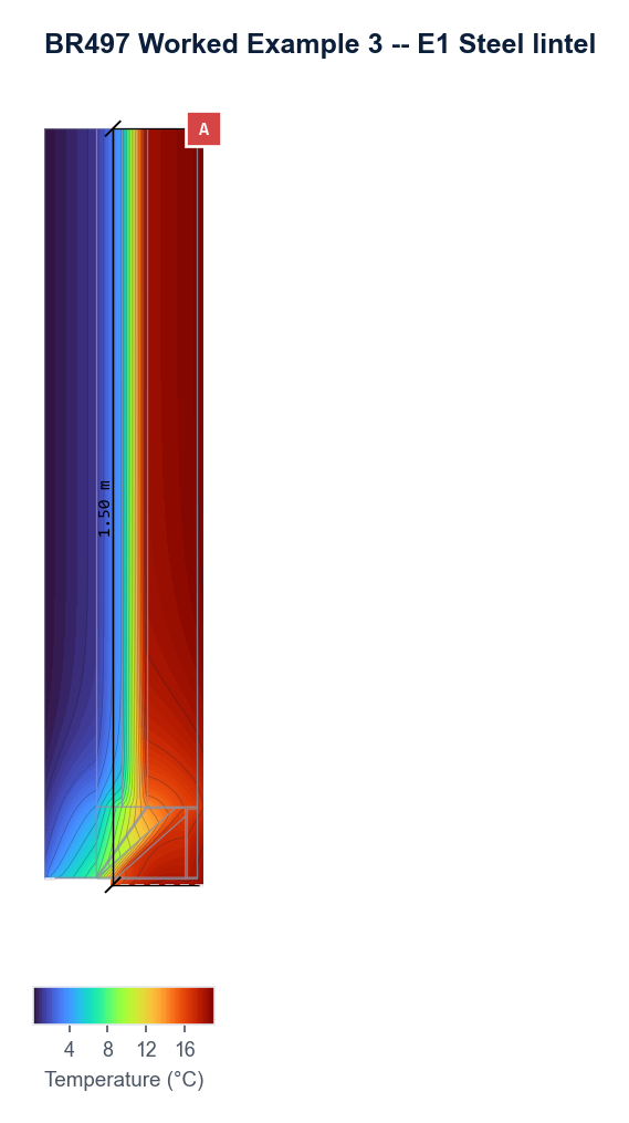
A numerical thermal bridging assessment was carried out for the junction designated as E1 — Steel lintel with perforated steel base plate, referenced in accordance with SAP 10.3 (13-01-2026) Table K1. The assessment was performed using two-dimensional finite element thermal modelling conforming to the governing conventions of BR 497 and in accordance with BS EN ISO 10211:2017. The linear thermal transmittance (ψ) was determined to be 0.412 W/(m·K). When evaluated against the default value of 1.000 W/(m·K) provided in SAP 10.3 (13-01-2026) Table K1 for this junction detail, the calculated figure demonstrated a significant thermal improvement, performing better than the default assumption. This calculated value was suitable for direct incorporation into the project energy compliance model.
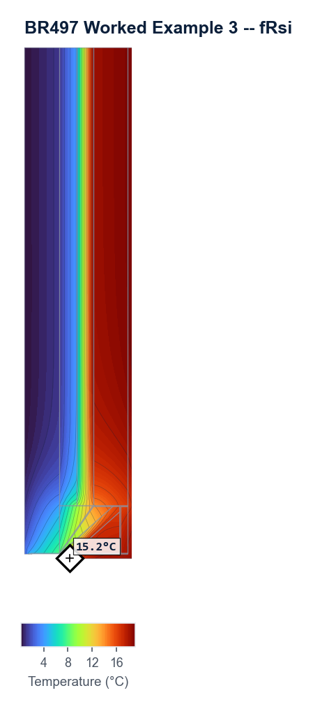
A surface temperature factor assessment was carried out for the steel lintel with perforated steel base plate junction (reference E1) in accordance with the guidance in BRE IP1/06, using standard assessment boundary conditions aligned with BS EN ISO 13788:2012. The assessment was performed to evaluate the risk of surface mould growth and internal condensation occurring at the internal surface of the detail. From the numerical thermal modelling, a minimum internal surface temperature of θsi,min = 15.22 °C was determined, yielding a calculated temperature factor of fRsi = 0.761. The calculated fRsi value exceeds the minimum threshold required for residential buildings, confirming that the junction design successfully passes the assessment criteria and presents an acceptable risk of mould growth.
The following condensation analysis is provided for professional completeness and risk-awareness — it is not itself a compliance criterion for this junction; only the fRsi check above governs BR497/Part L compliance. Where an annual assessment has been run, it is shown against the standard's own fixed UK-wide reference climate (EN ISO 13788 Annex C.1).
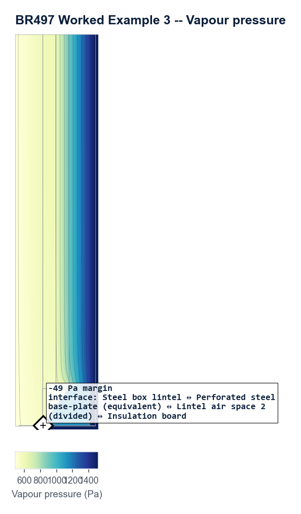
An annual condensation analysis to EN ISO 13788 §6.4, rigorous 2D node-wise method, shows the following:
| Month | Ext °C | Ext RH % | Ext VP Pa | Accumulated kg/m | Status |
|---|---|---|---|---|---|
| October | 10.0 | 83 | 1018.7 | 0.000 | Pass |
| November | 5.0 | 88 | 767.2 | 0.000 | Pass |
| December | 1.0 | 88 | 577.6 | 0.000 | Pass |
| January | -1.0 | 85 | 482.4 | 0.000 | Pass |
| February | 0.0 | 84 | 512.8 | 0.000 | Pass |
| March | 4.0 | 78 | 634.0 | 0.000 | Pass |
| April | 9.0 | 72 | 826.2 | 0.000 | Pass |
| May | 14.0 | 68 | 1086.5 | 0.000 | Pass |
| June | 18.0 | 69 | 1423.4 | 0.000 | Pass |
| July | 19.0 | 73 | 1603.2 | 0.000 | Pass |
| August | 19.0 | 75 | 1647.1 | 0.000 | Pass |
| September | 15.0 | 79 | 1346.5 | 0.000 | Pass |
Peak accumulated moisture over the annual cycle: 0 kg/m (per metre of section depth, not per m² of wall face)
No interstitial condensation forms at any point during the modelled year, and this construction passes the annual condensation check.
Materials
| Material | λ W/(m·K) | Vapour resistance | Emissivity | Source |
|---|---|---|---|---|
| Steel plate | 50 | Sd 200 m | — | BR 497 Worked Example 3, Step 5 — stated conductivity of the base-plate steel |
| Plaster-filled slot | 0.57 | µ 10 | — | BR 497 Worked Example 3, Step 5 — slots filled with plaster |
| Lintel air space 1 (cavity, downward) | 0.3199 | µ 1 | — | BS EN ISO 6946:2007 Annex B, as BR 497 §2.4 requires — resolved by Psiclops |
| Steel box lintel | 50 | Sd 200 m | — | BR 497 Appendix B, Worked Example 3, Table B3a — conductivity as published; vapour data from BS EN ISO 10456:2007 |
| Insulation board | 0.023 | µ 60 | — | BR 497 Appendix B, Worked Example 3, Table B3a — conductivity as published; vapour data from BS EN ISO 10456:2007 |
| Concrete block (inner leaf) | 1.13 | µ 60 | — | BR 497 Appendix B, Worked Example 3, Table B3a — conductivity as published; vapour data from BS EN ISO 10456:2007 |
| Cavity (unventilated, low-e) | 0.1129 | µ 1 | — | BS EN ISO 6946:2007 Annex B, as BR 497 §2.4 requires — resolved by Psiclops |
| Brick (outer leaf) | 0.77 | µ 10 | — | BR 497 Appendix B, Worked Example 3, Table B3a — conductivity as published; vapour data from BS EN ISO 10456:2007 |
| Plaster (dense) | 0.57 | µ 10 | — | BR 497 Appendix B, Worked Example 3, Table B3a — conductivity as published; vapour data from BS EN ISO 10456:2007 |
| Perforated steel base-plate (equivalent) | 6.9322 | Sd 200 m | — | 2D model solved separately for its equivalent conductivity, per BR 497 §2.3.1 |
| Lintel air space 2 (divided) | 0.285 | µ 1 | — | BS EN ISO 6946:2007 Annex B, as BR 497 §2.4 requires — resolved by Psiclops |
| Lintel air space 3 (divided) | 0.4137 | µ 1 | — | BS EN ISO 6946:2007 Annex B, as BR 497 §2.4 requires — resolved by Psiclops |
Download the solved geometry (JSON) — every polygon, boundary edge, material assignment and boundary condition exactly as calculated, including the conductivities derived for air spaces and referenced assemblies, so this example can be re-derived rather than taken on trust.
This is a fully static example — no live calculation was run to produce this page. It was generated once from BR 497, Appendix B, Worked Example 3 (E1 — Steel lintel with perforated steel base-plate)'s own published construction and boundary conditions, using Psiclops's own calculation engine. Try your own junction for free →